
SIDESTEP
ULTIMATE FRISBEE CLEATS
Footwear Design Innovation | Injection Molding | CAM, CNC | Tooling Design | Surfacing
Ultimate Frisbee borrows footwear from existing major sports, but it requires unique movements on the field. Between the three major motions of throwing, cutting, and jumping, throwing is the most unique to the sport and least accounted for in available footwear. I designed, prototyped, cut tooling, injection molded, and tested a lateral traction concept created specifically for Ultimate. The custom heel feature helps a thrower plant their foot without slipping or rolling an ankle while pivoting and stretching around a defender.
SUMMARY


IDEATION


The lateral heel was the focus as the main area of ground contact. From a few quick concepts, I decided to focus on a rim contour around the lateral heel because of its mold simplicity, ability to avoid mud build-up, and integration with existing plate contours.
concept development


An old soccer shoe was taken apart to get a sense of construction and outsole geometry. There were many more layers and the outsole was much thinner than expected. After deciding on a concept, I mocked up the physical form with polymer clay on an existing shoe. Higher resolution form concepts were then modeled and prototyped in HDPE with 3-axis CNC machining. The model was not yet designed for all manufacturing considerations like part thickness.
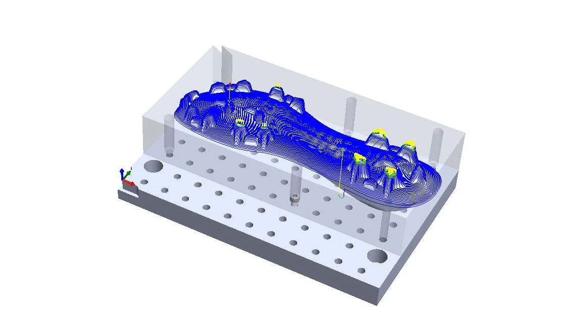
cnc outsole


Although the HDPE was soft and cut quickly, feeds and speeds had to be adjusted to avoid melting at the cutting location. The soft plastic was also tricky to fixture in a vice because it required just the right amount of compression to counteract slipping without causing any bowing. Both the top and bottom of the outsole were cut, so the parts needed to be flipped and realigned halfway through. I made sure to leave some thin-web material around the part to keep it stationary until cutting was complete.
disassembly + REASSEMBLY


Existing football cleats were disassembled by baking them at low heat in a toaster oven, melting the adhesive. The custom-machined soles were then attached to the upper with contact cement.
form prototype


tool library
After assembling a form prototype, a functional prototype concept was modeled, accounting for more injection molding requirements like parting lines, part thickness, and minimum feature fillet sizes. This was followed by tooling design, taking more requirements into account like maximum mold base dimensions, sprue location, and total part footprint.
I used various cutting tools for mold fabrication. Initially, narrow and deep channels were machined with extra-long square end mills at high speed and low feed to prevent breaking. This limitation resulted in extremely long cut times, some exceeding five hours. A breakthrough in the process came with the discovery of tapered end mills, which more than halved the cut times and created drafted features without extra finishing passes.
mold machining
More than sixty hours of machine time went into fabricating the final mold out of two 8.5" X 12" X 1.5" aluminum plates. Mold design was much less straight-forward than expected and pushed almost every limitation of available CNC and injection molding machines.
Since the part line was a contour and not planar, a three-dimensional parting surface needed to be designed and machined with tight tolerances to avoid flash. As a result, cutting tool length became a critical issue. Thin and deep cleat stud cavities needed to be machined without crashing the tool holder into the mold. Accounting for tool radii in the form of fillets also presented a tricky surface modeling challenge, since the lateral traction feature required multiple contours to converge in the same location.
machined mold


Sheer part size also resulted in significant challenges. In order to fabricate a sole of my shoe size (for testing) while staying within the maximum mold size, the cavity had to be cut diagonally across the mold halves, with some areas less than half an inch from mold edges and less than a quarter inch from exterior mold surfaces.
injection molding
The injection molding machine available also had part volume and footprint limitations driven by holding pressure that required several design iterations. A full sole footprint wasn't possible, so openings between stud features were designed, significantly decreasing the effective area. This did weaken some areas of the sole, so additional layers of structural support might be required in a final product. Fortunately, these openings also addressed the challenge of a fixed sprue location in the center of the mold base. Finally, part removal was initially a concern since ejector pins weren't possible with the mold base provided. Luckily, the part's deep features were balanced enough between the two mold halves that parts actually ejected themselves during mold separation.
factory visits
In addition to visiting local injection molding houses, I toured a local post-industrial recycling facility, which donated polypropylene that was reground at their facility. All of my parts were molded using this recycled material.
finished parts


Color pigments were added, highlighting mold flow and creating this gradient of varying opacity.
FUNCTIONAL PROTOTYPE


PROTOTYPE TESTING


Functional prototypes were tested in game situations like outstretched throwing around a defender. Initial tests were successful, with the lateral rim feature providing additional traction when planting with the side of the heel to allow for extended, low-release throws. The heel rim also provided stability, helping to prevent the foot from rolling over.
key learnings
Consider manufacturability from the beginning—I could have avoided having to recreate the entire CAD model if the original iteration had been designed for injection molding.
Isolate product features of interest for testing—instead of designing the entire cleat plate, I could have focused on creating a modular system to test various lateral traction designs. The final plate needed to be separated into two components anyways for improved upper/tooling alignment.
Leverage existing/off-the-shelf components—repurposing an existing pair of cleats was the difference in making it possible to test a functional concept within the time frame.
Consider performance impacts of cosmetic/material decisions—I back-painted the final parts to represent the visual design intent, but the parts delaminated at that interface after playing on field. Instead of polypropylene, a different polymer more suited to bonding and extended wear could be explored.